Building a Light-Activated Morse Code Translator
Last week, I dug up an Arduino kit I had bought a few years prior and started to tinker with it again. Because it has been a while since I have done anything with Arduino, or electronics in general, I followed a couple practice tutorials. Just the basics; lighting an LED, building a binary counter, the classics. However, before I even started, I already knew what I wanted to do as my first “real” project: a morse code translator. At first, I was unsure whether the project would utilize sound or light as the input. But morse code was designed to be transmitted audibly, so of course I went with light.
References
Components
Everything I used for this project can be obtained from this Elegoo Arduino kit.
- 1x Arduino Uno R3 Board + USB Connector
- 1x 10k Potentiometer
- 1x 1602 Character LCD
- 1x Photoresistor
- 1x 10k Ohms Resistor
- 19x Jumper Wires
Building the Hardware
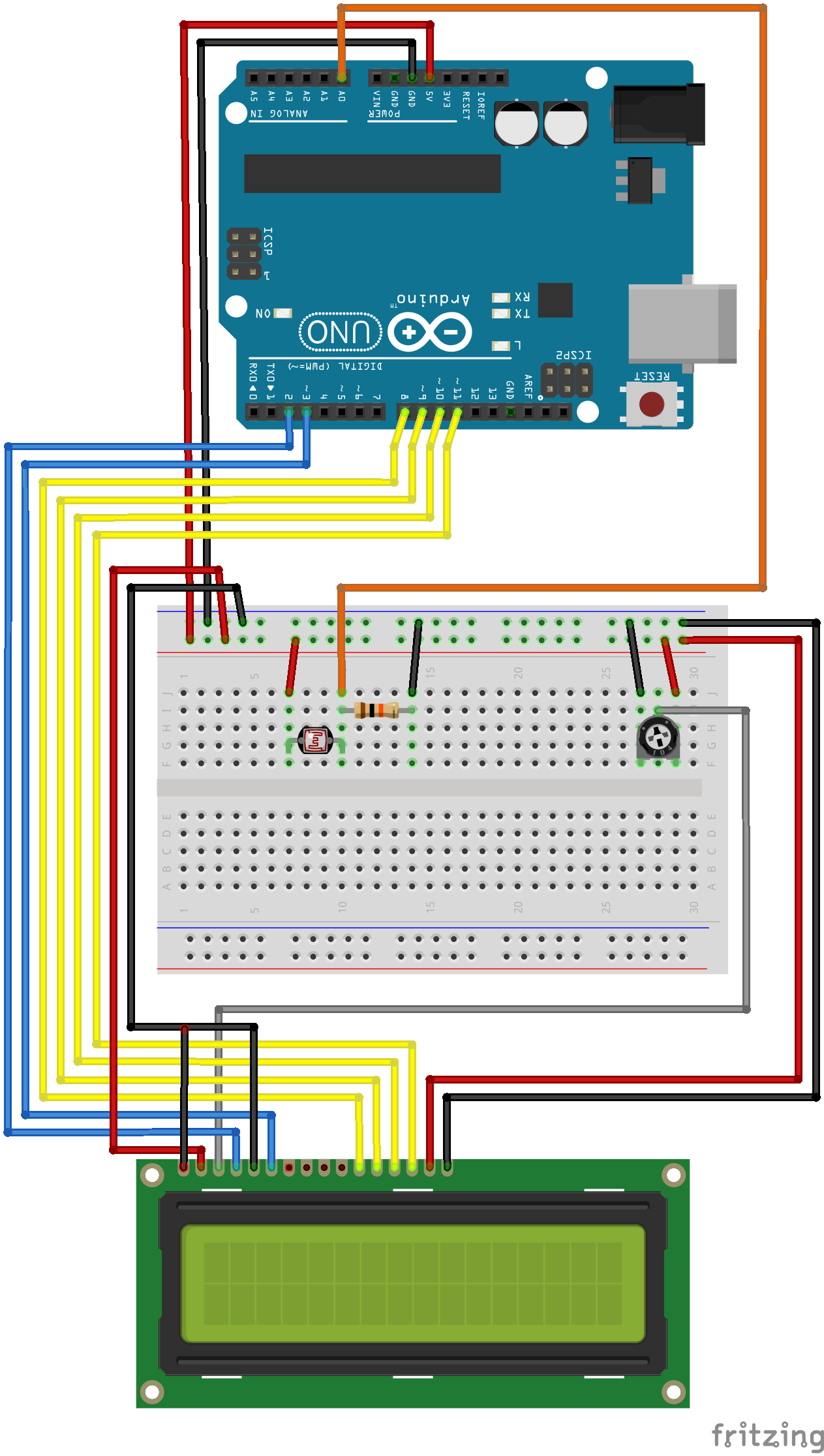
The electronics component for the project is actually rather simple. If you have not already seen it from the references, here are the schematics again. For someone who is unfamiliar with electronics, this may seem complex at first glance; however, the vast majority of the diagram is used for the LCD panel, which acts as the primary output for this device. The configuration is pretty standard, and actually comes straight from this tutorial, with a the only real difference being the actual ports the pins are connected to. This circuit also include a potentiometer to easily control the contrast of the display.
Besides the LCD, the only other component is a photoresistor, which is a small component that change in resistance depending on how much light it receieves. In other words, it is a sensor that detects light. Similar to how the LCD is the only main output, this photoresistor is the only main input. The photoresistor is wired independently from the LCD and sends its signal to an analog port on the Arduino. You may notice in the schematics that there is a resistor attached in series to the photoresistor. Why is that? Well, I don’t really know but this guy on StackExchange does.
Writing the Code
It has actually been a long time since I had written any code for Arduino, and that was also the last time I had written anything remotely resembling C++ at all. To start, I just used the Arduino IDE to make sure I was able to write to the LCD and read from the photoresistor. That worked well. However, I did not like the idea of keeping all of the logic it would need in one file, and was not a fan of Arduino’s sketch concatanation. So I ended up switching to straight C++, using the VSCode Arduino extension.
By far, the biggest roadblock I ran into is how to manage the mapping between characters and their respective Morse code sequences. Coming from a C# and JavaScript background, my mind initially went to a map or dictionary. I just need a dictionary that maps characters to lists of integers, right? It worked well. First of all, I defined two constant integers to keep track of dots and dashes: DOT = 0 and DASH = 1. Then I defined a couple of types: MorseSequence, a vector of integers; MorseEntry, a key-value pair of char to MorseSequences; and MorseMap, the map itself. The only problem was I could not create the map at the root of the file, so I had to write a GetMorseMap function to create and initialize it. But that was just a small inconvenience. I wrote a small program in main to check, compiled, ran the app, and everything was perfect. Until I built it as an Arduino app.
As it turns out, the Arduino compiler does not come with the C Standard Library (cstdlib), which includes practically everything I used for the Morse map. One option was to pull in a library; there were several libraries that just copies some of the functionality I needed from cstdlib to Arduino. I tried them out, but the transition just wasn’t as smooth as I had hoped. So I decided to scrap everything and just went with a backup plan. This meant that I no longer had access to vectors or maps. Instead, I redefined MorseEntry as the following structure type:
struct MorseEntry
{
  char character;
  int sequence[5];
};
Because the sequence was no longer stored as a vector, and arrays in C++ are fixed-sized and filled with the default value for its type, I had to tweak the constants for the commands. DOT was now 1, and DASH was now 2. Good thing I went with integers instead of booleans. MorseMap was now just an array of MorseEntrys. Since I no longer had access to the map functions, I just wrote a couple helper functions to look up with values from the MorseMap.
After figuring out the map, the rest was pretty straightforward. For my first attempt, I just used a few global variables to keep track of timestamps and sensor state. Within the Arduino runtime loop, it first checks the stored state value and compared that to the current state.
// If the stored state is off, but the current state is true, the light has been "activated".
if (!state && isOn)
{
  state = true;
  lastChange = t;
}

// If the opposite is true for both, then the light has been turned off.
if (state && !isOn)
{
  state = false;
  lastChange = t;

  if (diff < MORSE_COMMAND_THRESHOLD)
  {
    currentSequence[currentIndex] = DOT;
  }
  else
  {
    currentSequence[currentIndex] = DASH;
  }

  currentIndex++;
}
Once the new state has been determined, it compares the time since the last change against a series predefined thresholds to determine what action to take.
// If the character threshold has passed and it's in the middle of building a sequence, close and read the sequence, and print the result
if (!state && diff == NEW_CHARACTER_THRESHOLD)
{
  if (currentIndex > 0)
  {
    lastChange = t;
    char character = ReadMorseSequence(currentSequence);
    lcd.print(character);
    for (int x = 0; x < 5; x++)
    {
      currentSequence[x] = 0;
    }
    currentIndex = 0;
    charSent = true;
  }
}

// If the space threshold has passed and the last action taken was printing a character, print a space.
if (!state && diff >= SPACE_THRESHOLD)
{
  if (charSent)
  {
    charSent = false;
    lcd.print(" ");
  }
}

// If the reset threshold has passed, clear the board
if (!state && diff >= RESET_BASE_THRESHOLD)
{
  reset();
}
Finally, just for a little bit of extra flair, the LCD cursor blinks every 400ms.
if (t % 400 == 0)
{
  lcd.blink();
}
I have since refactored the code, mostly to move most of the logic into their own dedicated classes. You can find the final codebase on GitHub.